 One of the challenges I’ve encountered in the past is trying to find and easy way to design architectural models on the computer. I’ve worked with several 3D programs as well as an assortment of CAD suites, but for the simple task of creating basic wireframe drawings for model railroad structures, I’ve settled on using Adobe Illustrator. I find that Illustrator allows me to develop drawings quickly, as well as create an interactive reference that I can use during construction. I’m not going to go into a full-fledged tutorial on how to use Illustrator – like other programs of its ilk it does have a average/steep learning curve, and isn’t the cheapest program available – it’s intended for use in the graphic design industry so the majority of individuals don’t have access to the program. For those who do have it and use it, here’s a quick outline as to how I create my scale drawings.
Step one: create a representative scale
While Illustrator can express all objects as imperial units, trying to design a full size structure using the program is impossible as the page margins are quickly exceeded by any 1:1 drawing. Instead, I’ve found that it’s easiest to use cm as a representative unit for feet. Ie. 3cm = 3feet. Thus, I start a new document using cm for the basic units and rulers.
Step two: express fractions as decimals
As every foot has 12 inches, it’s difficult to design components without first translating the measurements to decimal equivalents. To do this I use the following table.
1″ = 0.08cm
2″ = 0.17cm
3″ = 0.25cm
4″ = 0.33cm
5″ = 0.42cm
6″ = 0.50cm
7″ = 0.58cm
8″ = 0.67cm
9″ = 0.75cm
10″ = 0.83cm
11″ = 0.92cm
With this, a door that is 3′ x 6’8″ becomes 3cm x 6.67cm. Using this, I can specify exact measurement using the transform tool, as well as add two dimensions together easily.
Step three: scale to N
Once I have finalized my drawing, I reduce the overall size to 13.72% of the original to create a full-size N scale rendering. Because we are working in cm, the drawing has already been scaled down considerably – it now only needs to be reduced further to be an exact 1:160 rendering.
Step four: build with the computer
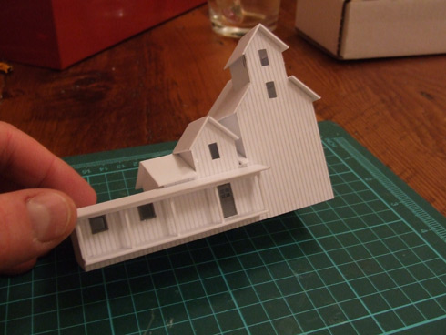
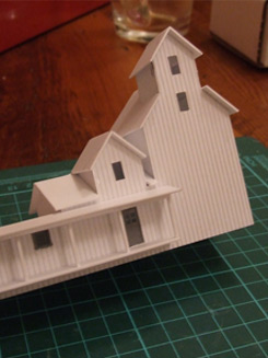
I now have the option to print the drawing at 100% and use this hard copy as a reference, or I can simply pull the drawing up on the screen of the computer and work with it as I build. I find the latter method easier as clicking on any aspect of the drawing will give me exact measurements expressed as cm. So in the case of my 60′ long feedmill, selecting the entire drawing (and referencing the transform tool) tells me that I need to cut the base of the structure 11.43cm long. In the case of the second decimal place, I typically round this measurement to the nearest decimal. Doing so does cause some inaccuracies in the build, but usually 1mm can be compensated for quite easily.
So there you have it. Again, for those unfamiliar with the program this will likely be a rather cryptic explanation. I hope that for those of you who do use Illustrator, this may offer an easier option for scratchbuilding then graph paper and pencils.
Based on the drawing I completed two evenings ago, here is the progress on the feedmill: I’ve managed to completely construct the basic structure. All that needs to be done now is add some paint and details.