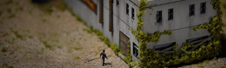
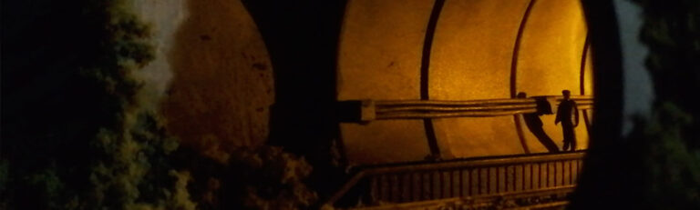
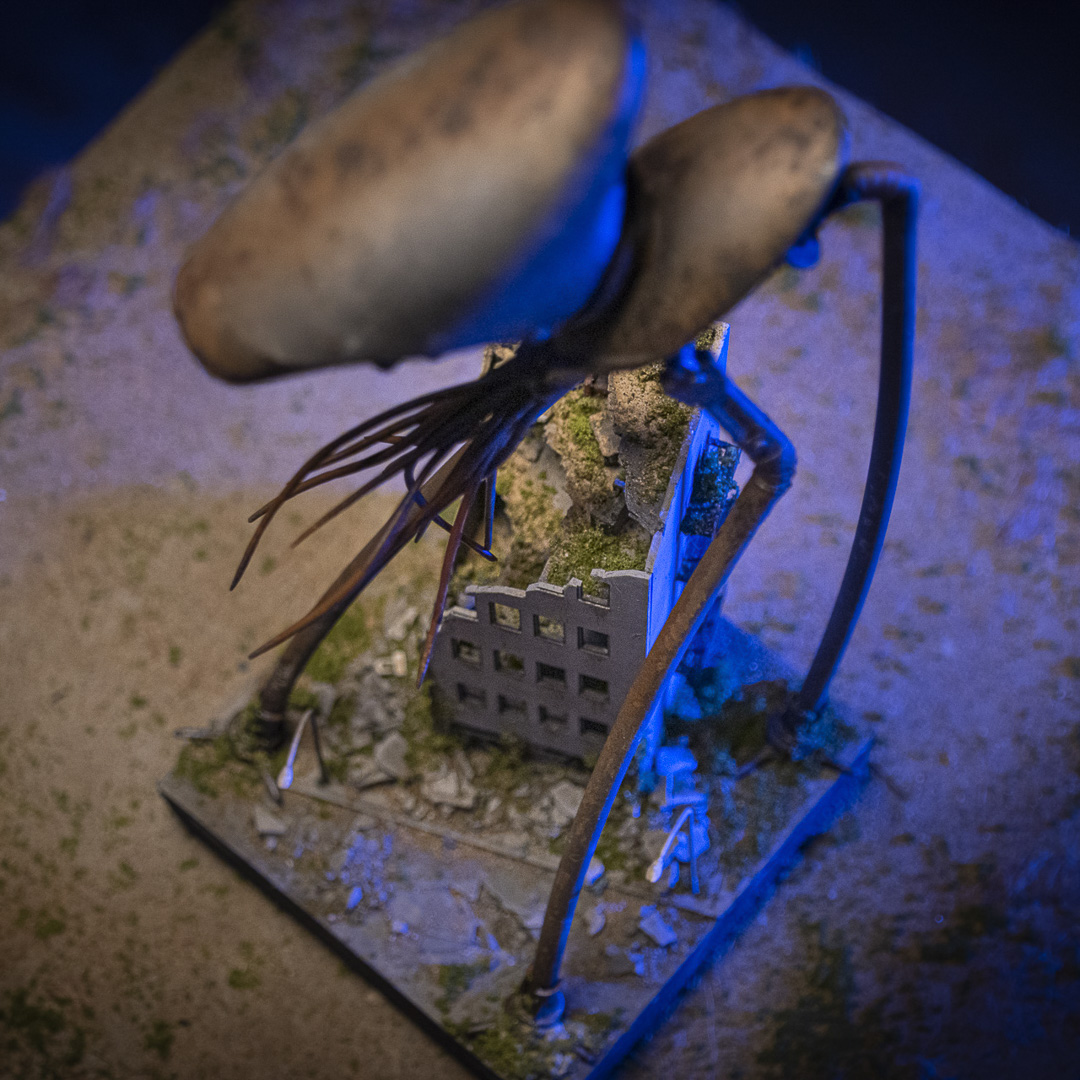
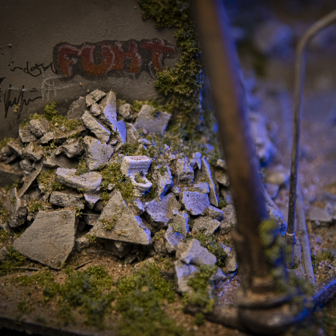
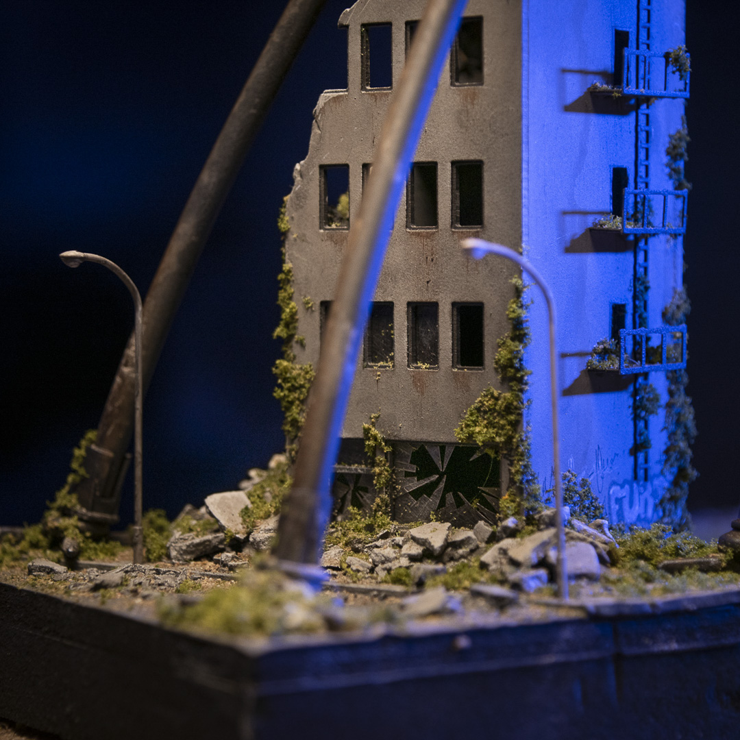
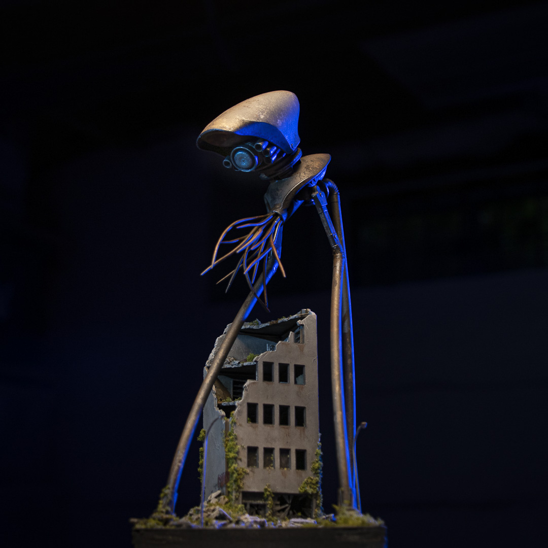
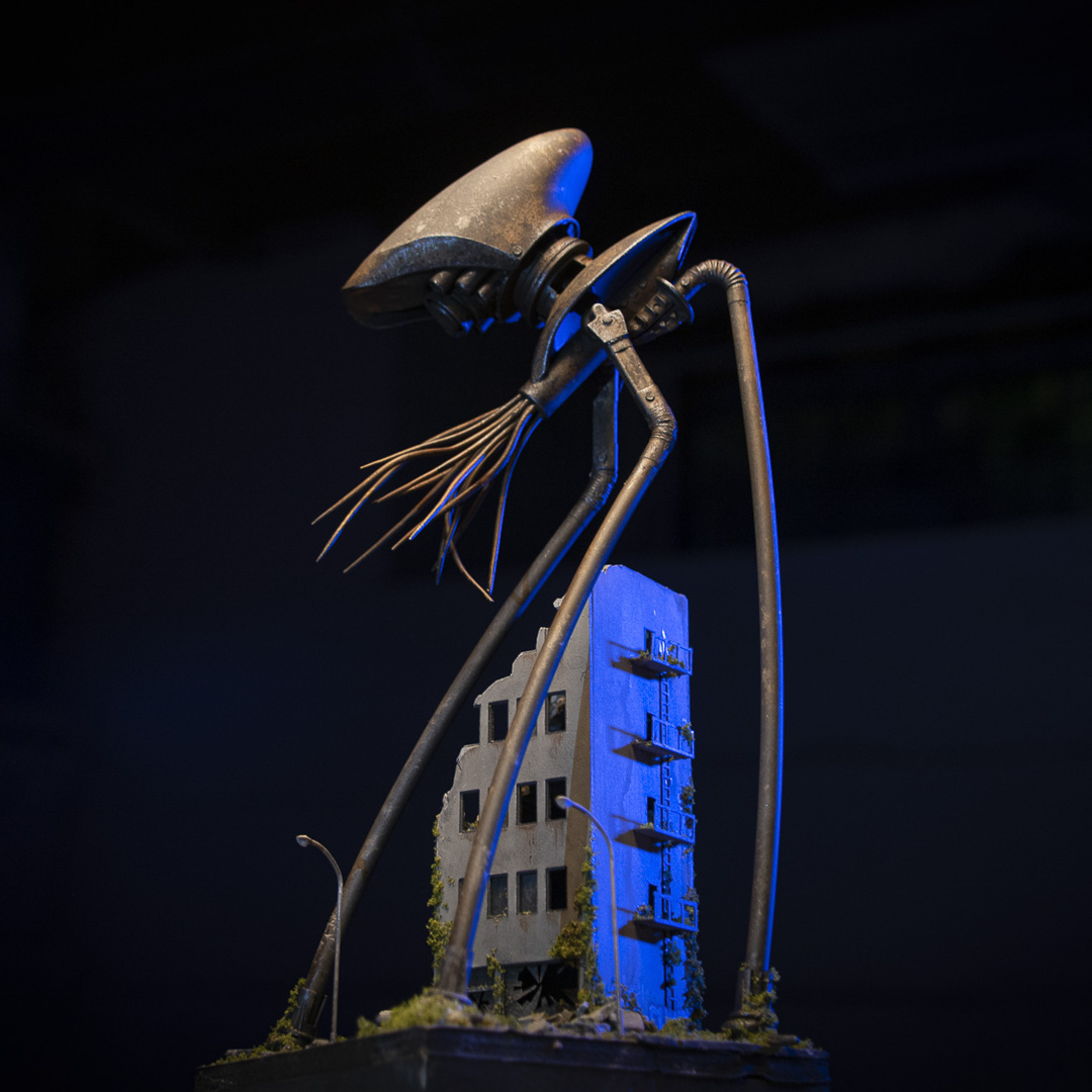
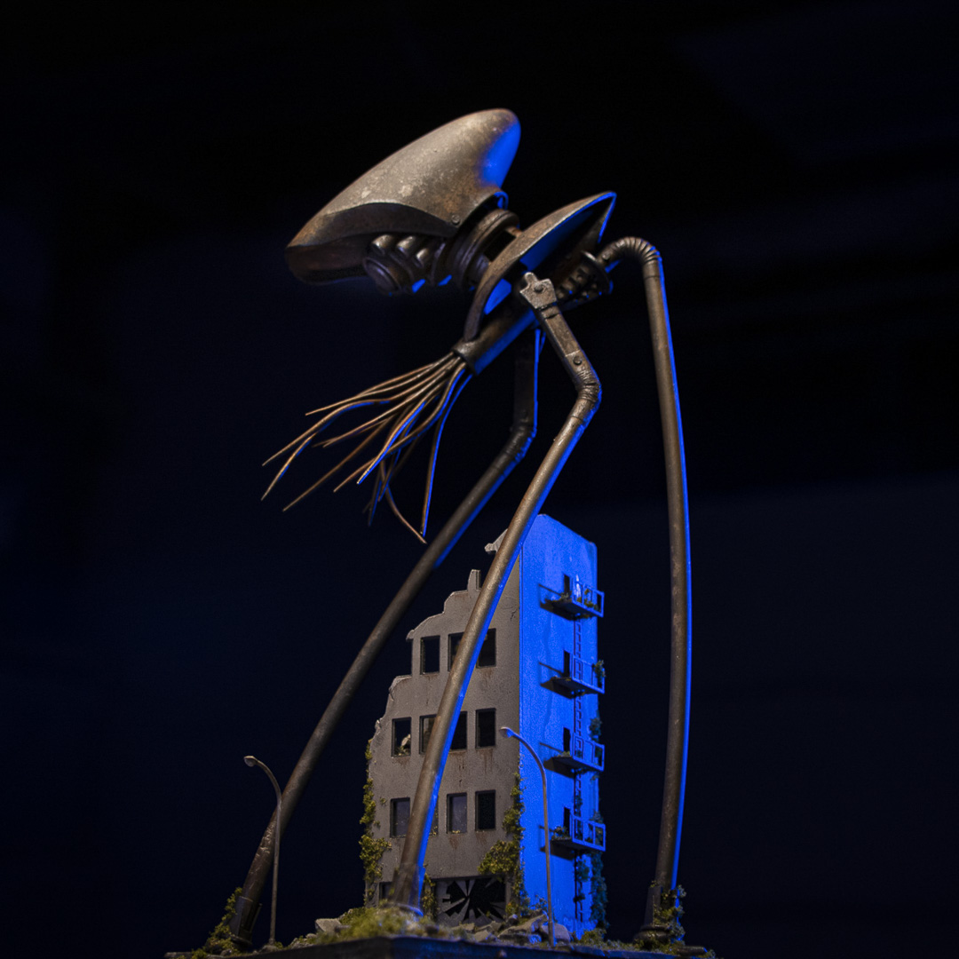
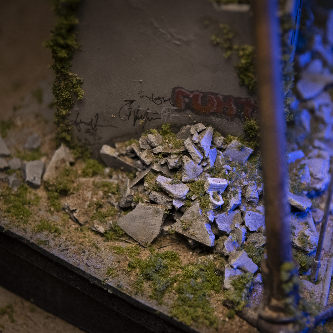
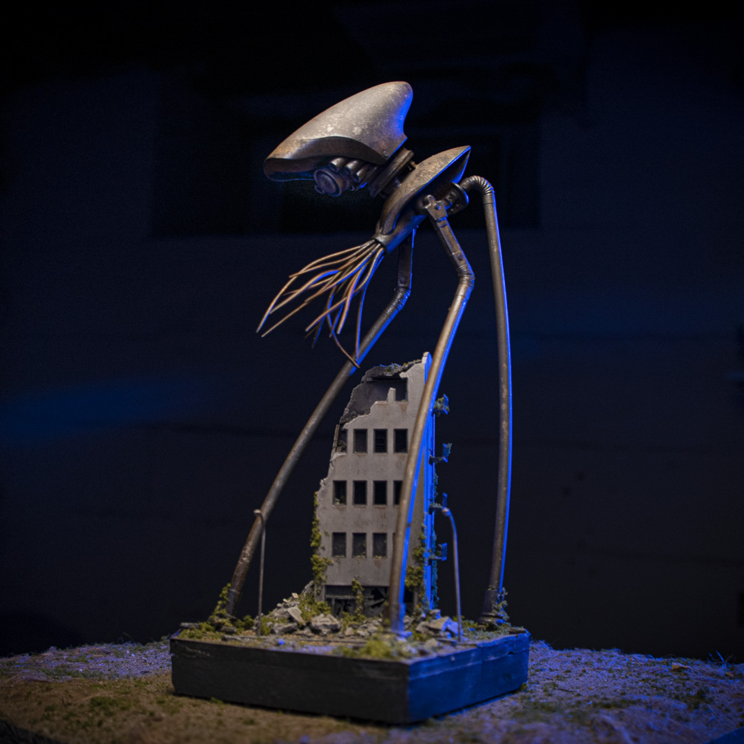
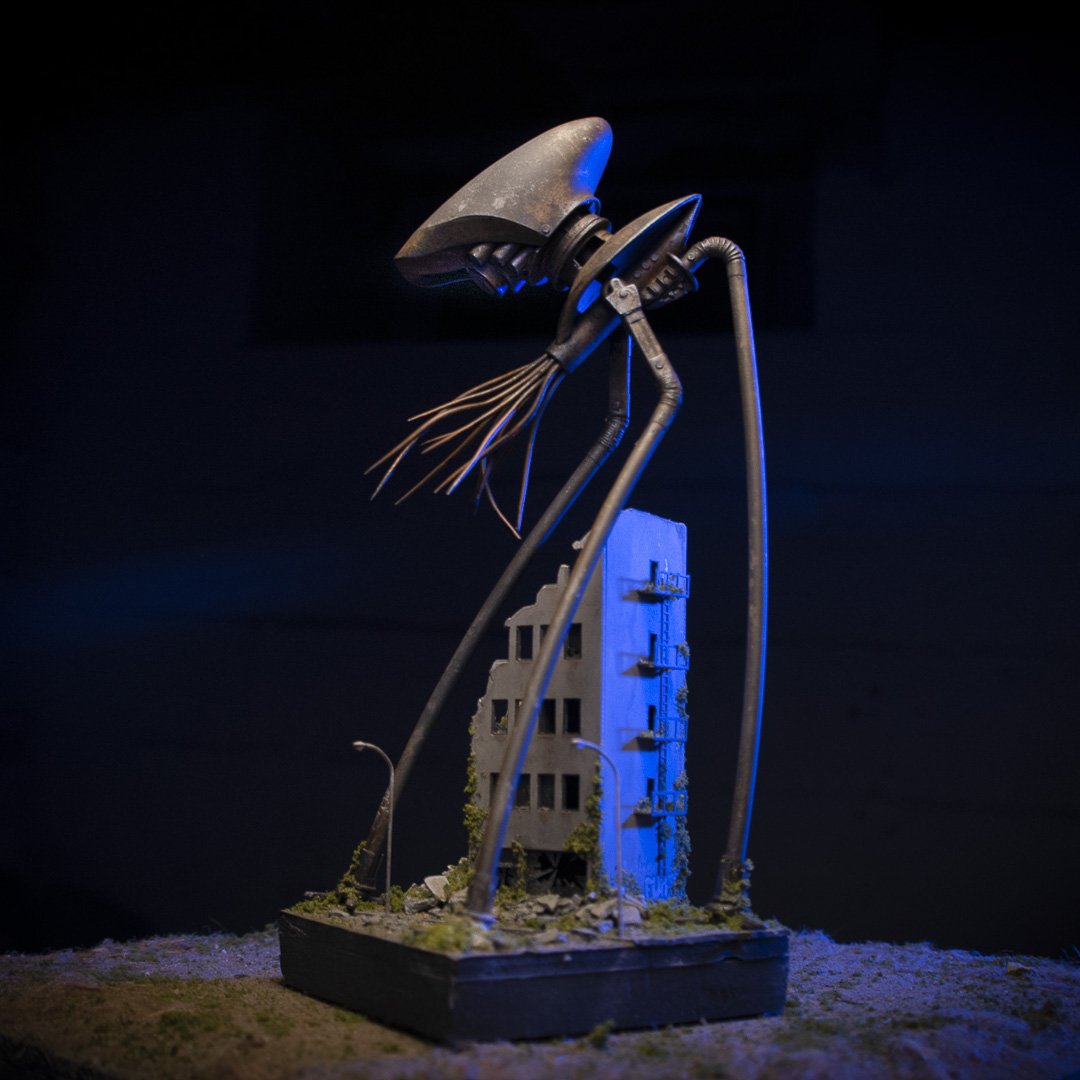
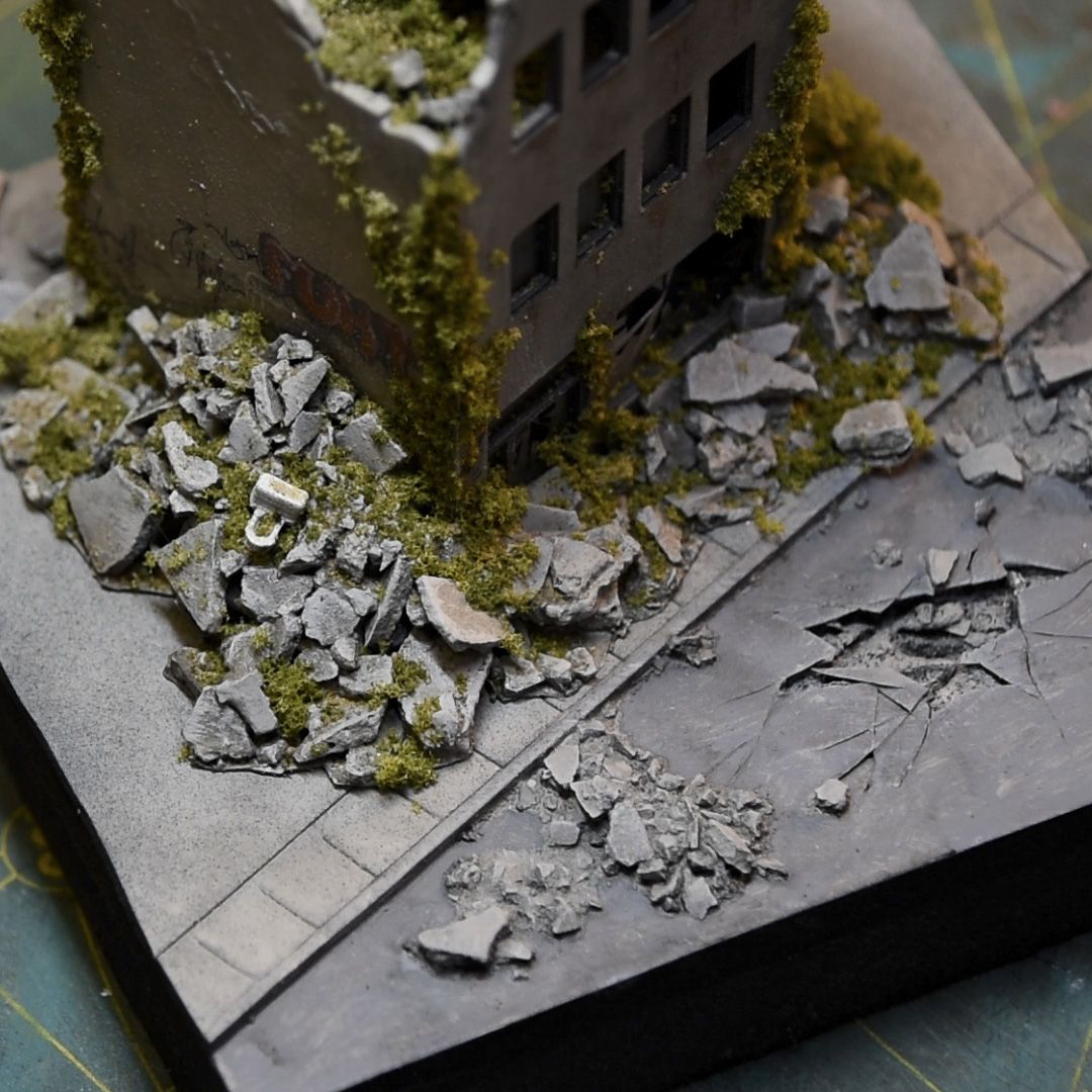
On October 30th, 1938, CBS radio broadcasted a Halloween radio drama narrated by Orson Wells that became famous for causing panic among its radio audience. That episode was H. G. Wells’ War of the Worlds. This is week four / project four of my five-week ‘Halloween-themed’ build challenge and I completed a 10×10 diorama inspired by the radio drama.
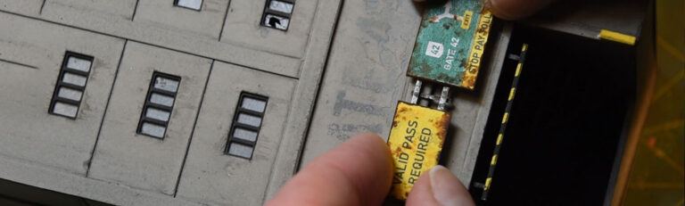
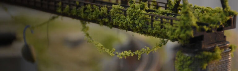
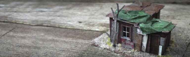
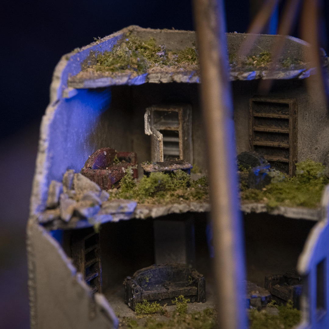
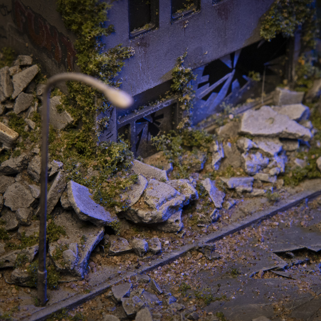
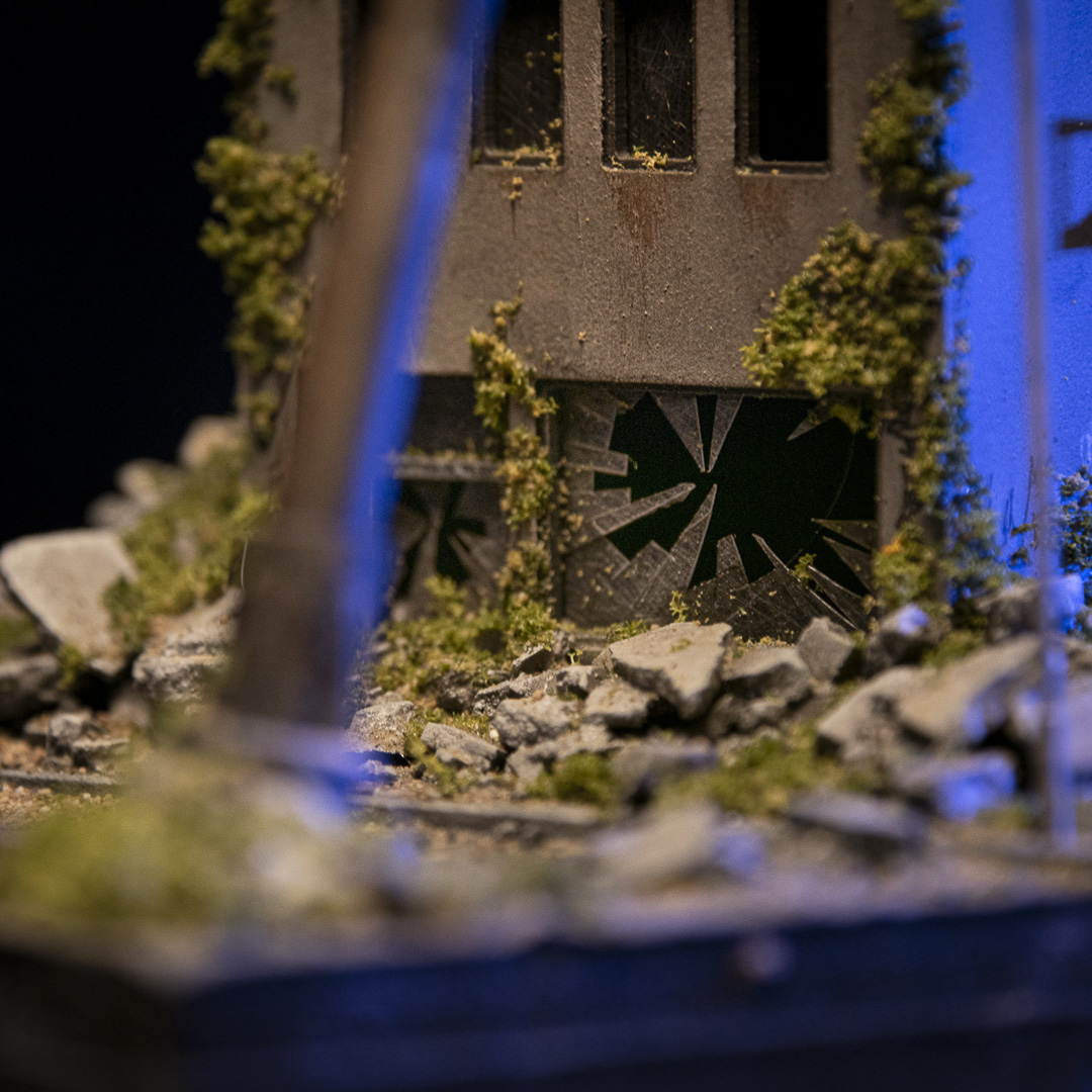
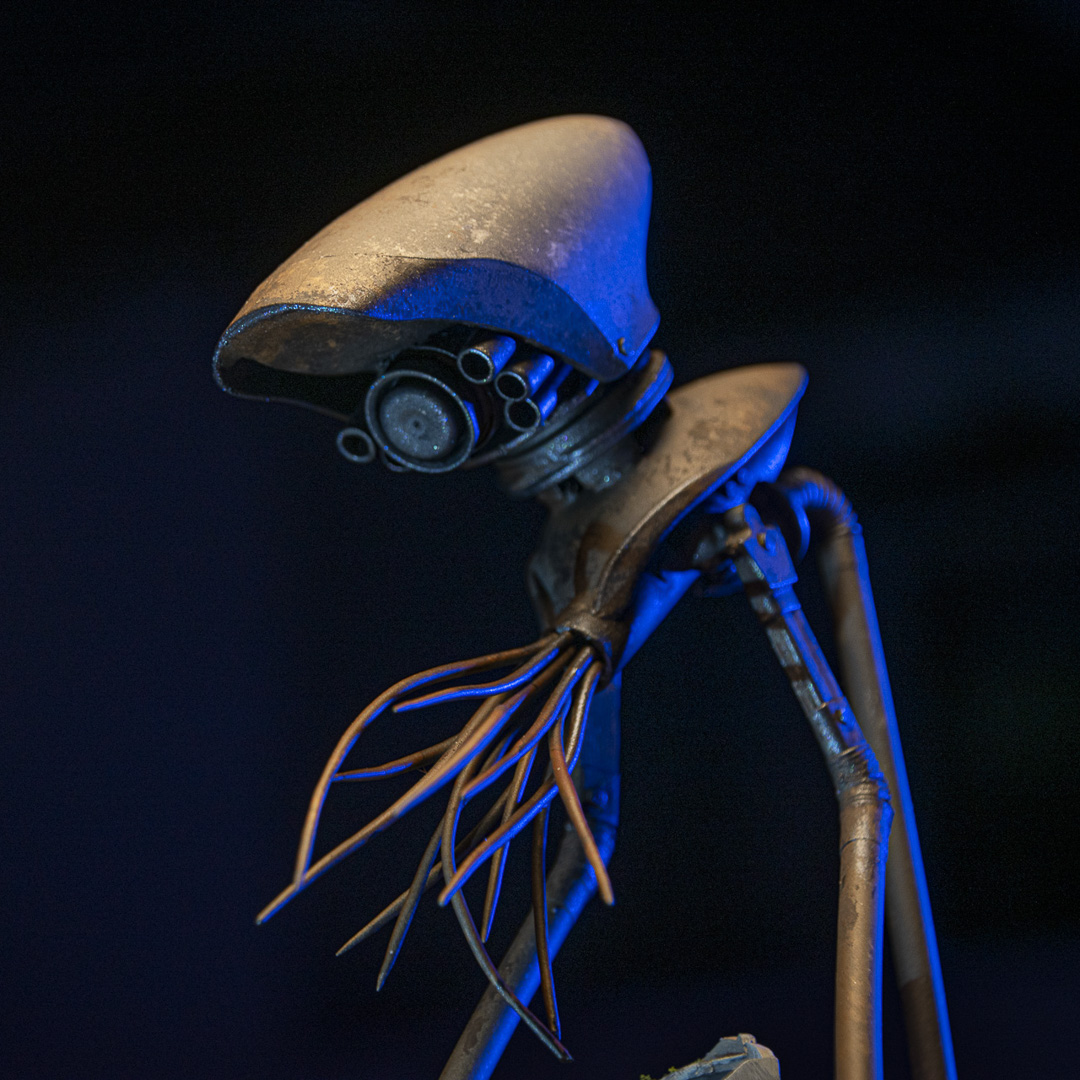
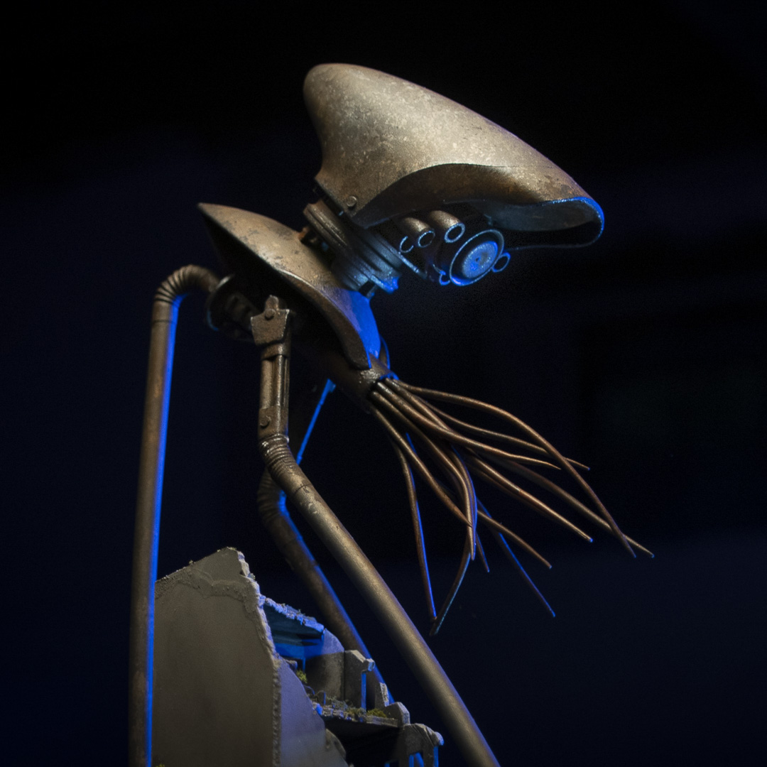
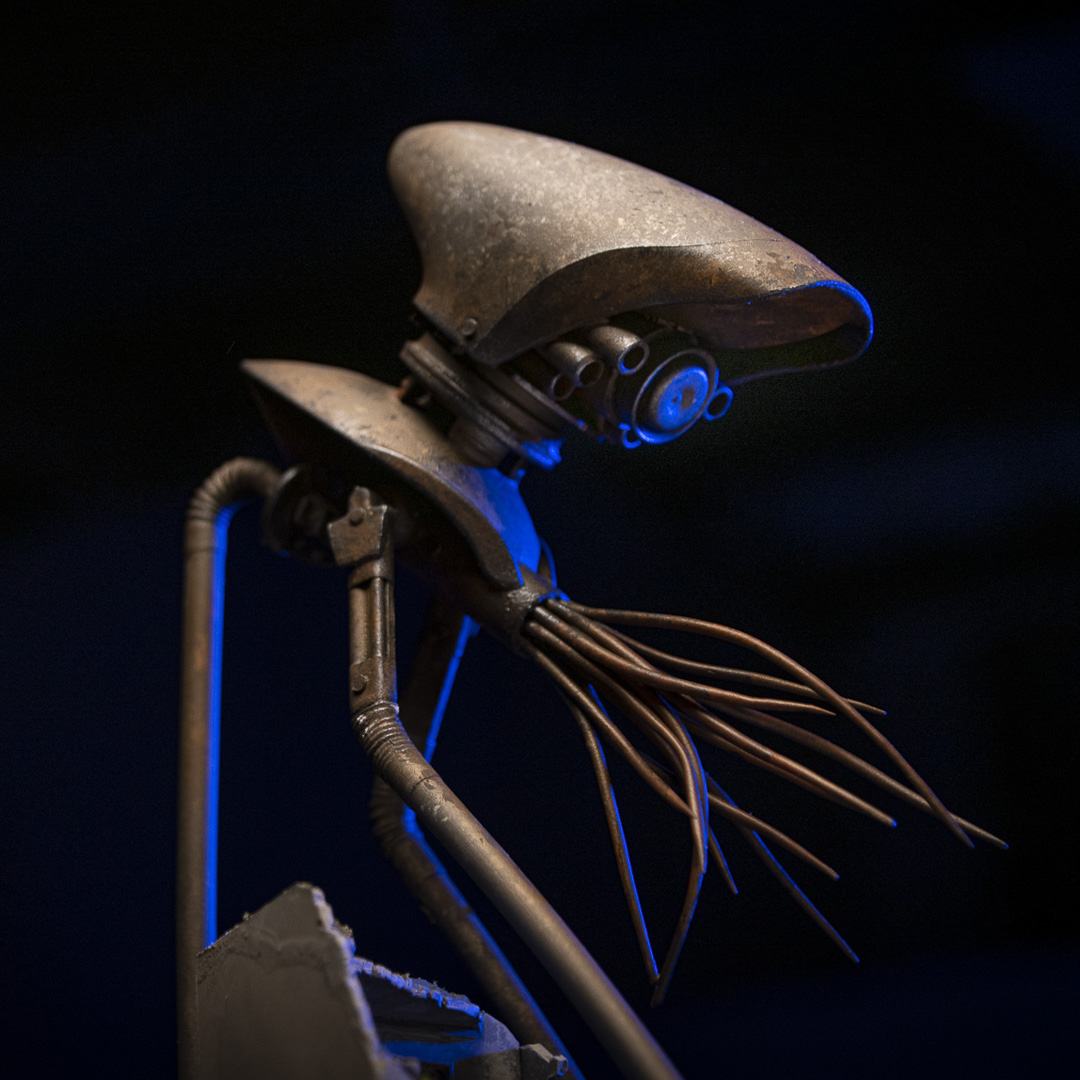
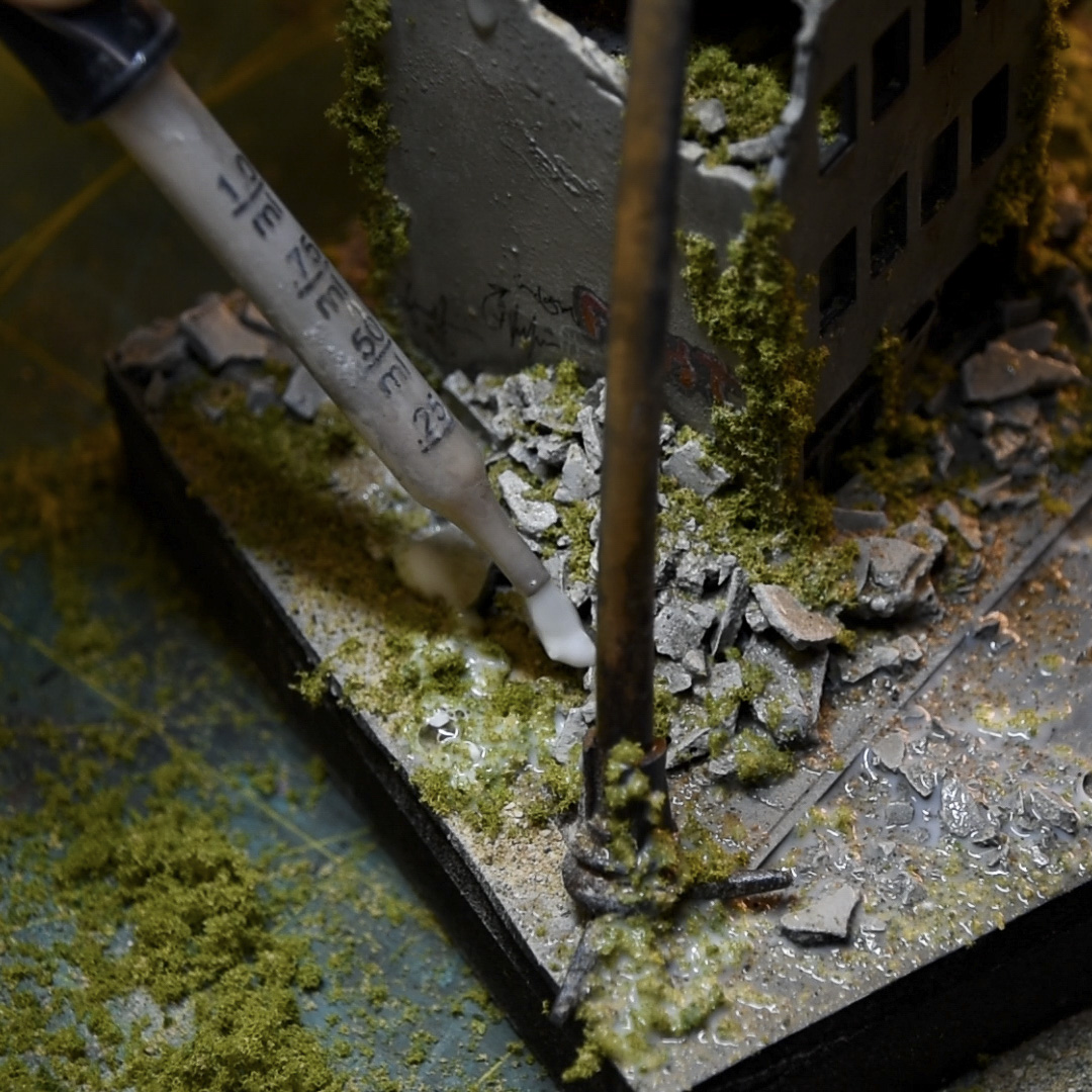
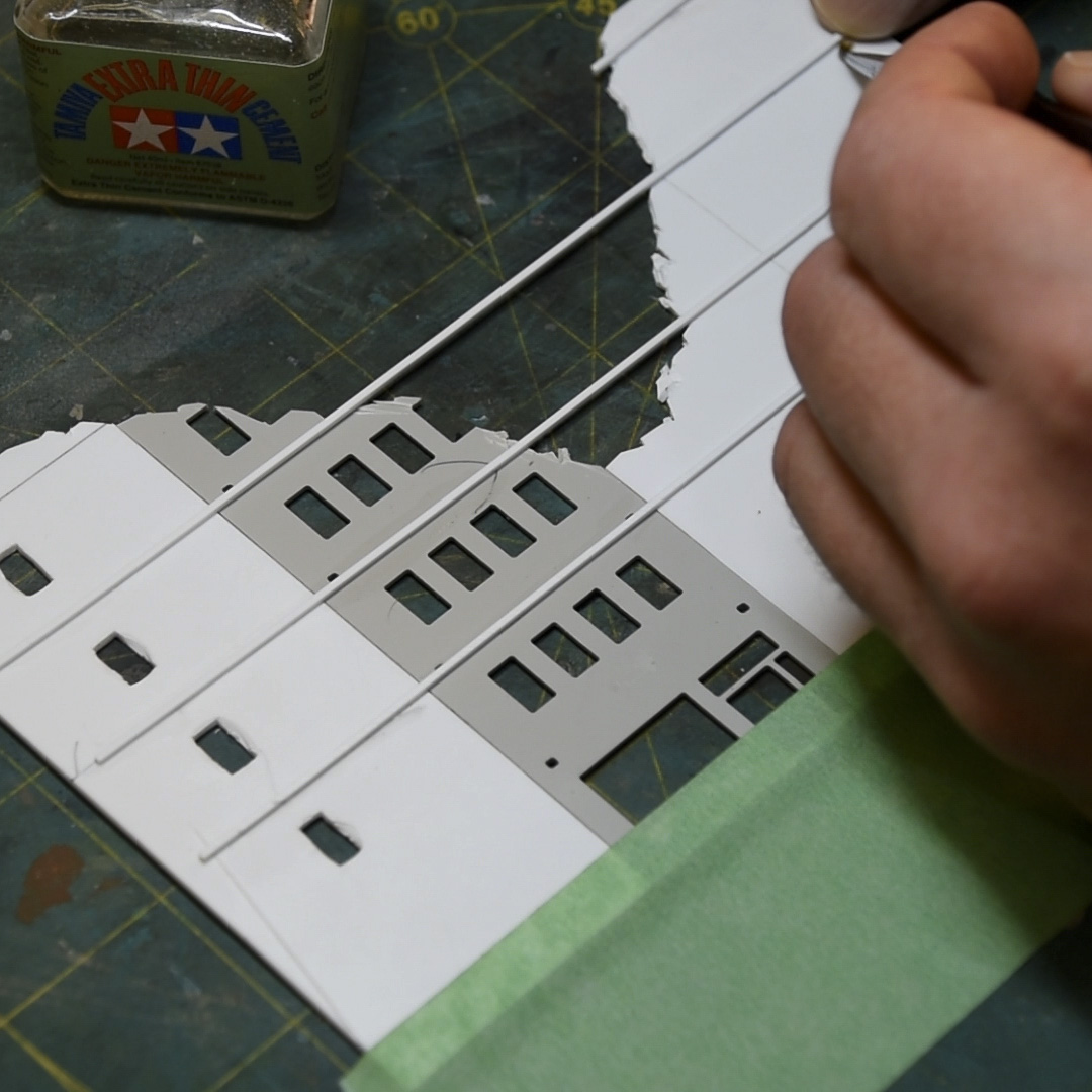
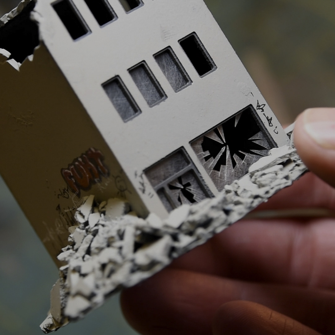
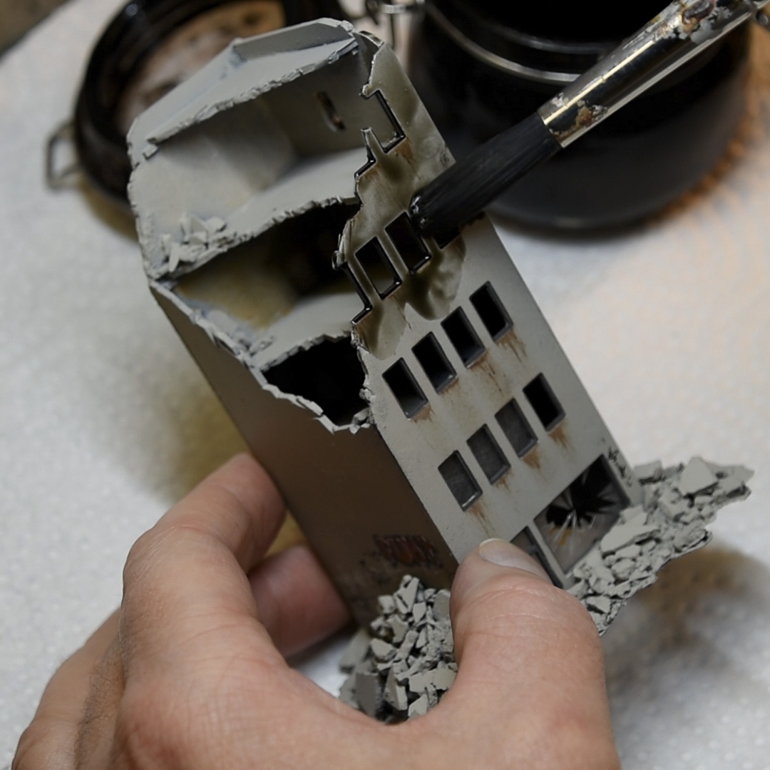
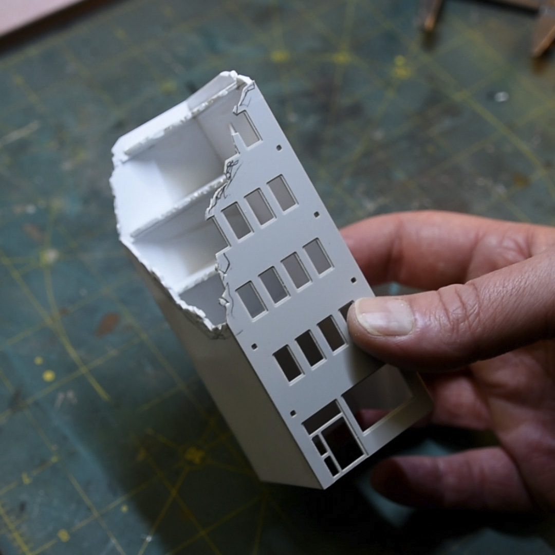
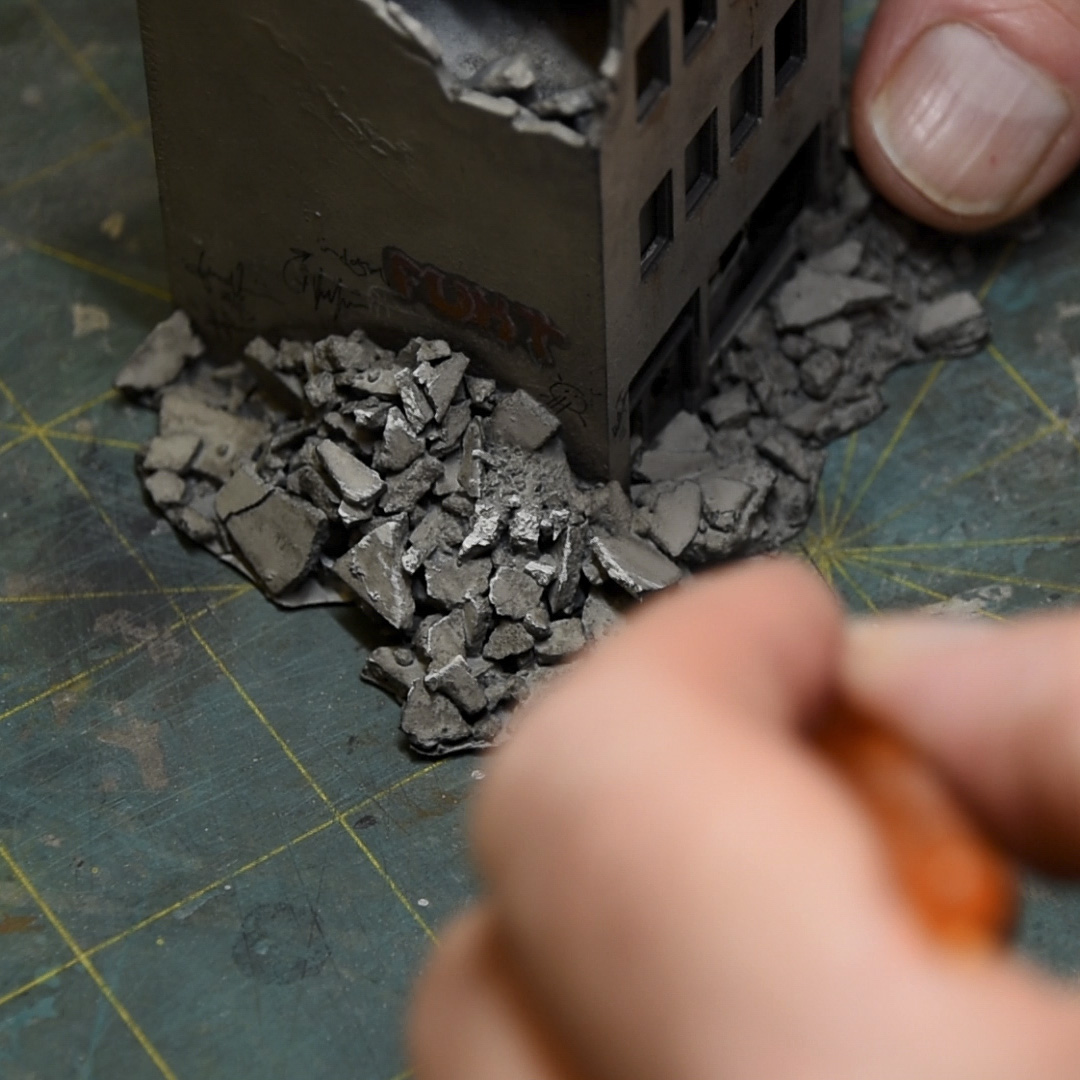
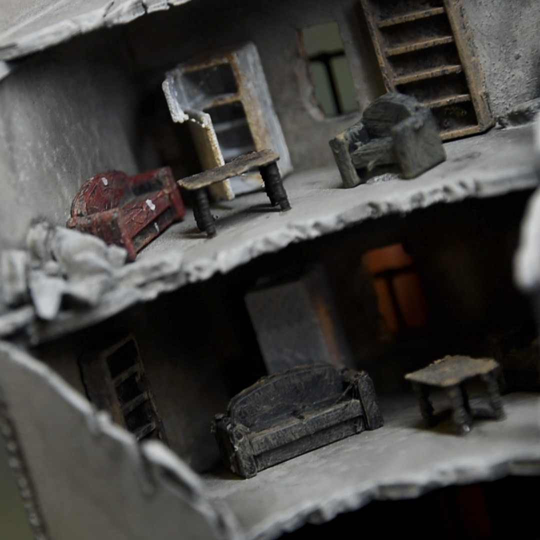
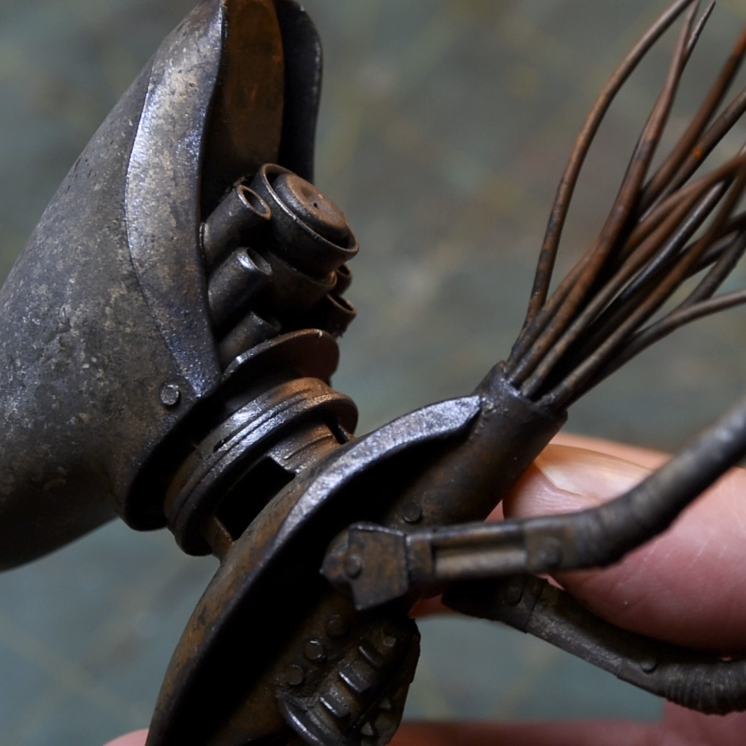
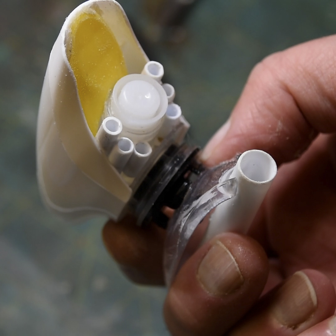
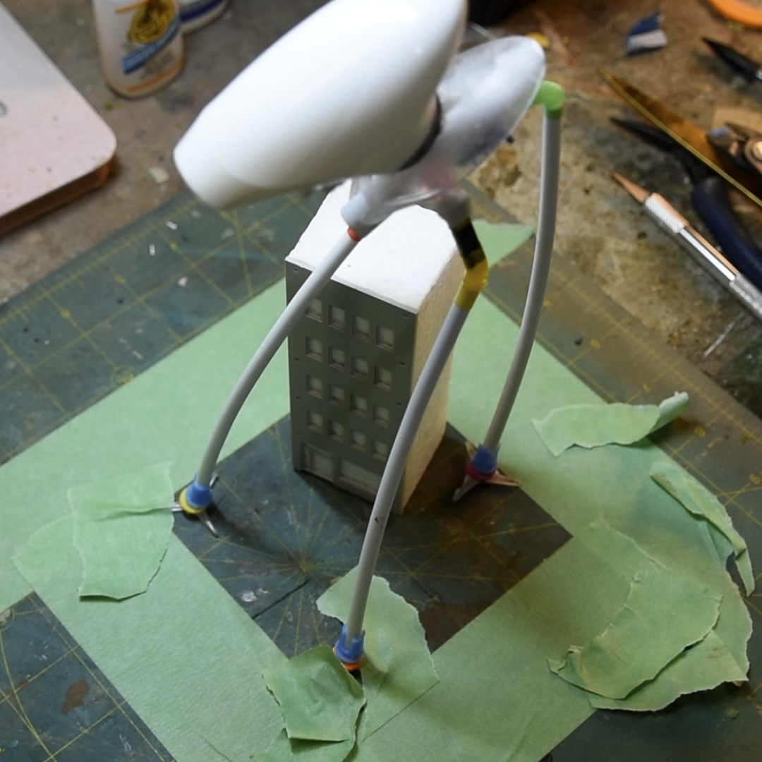
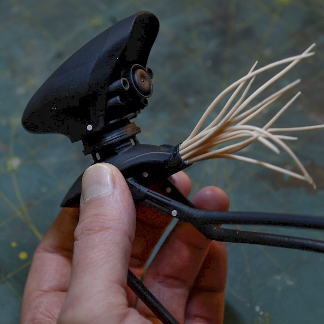
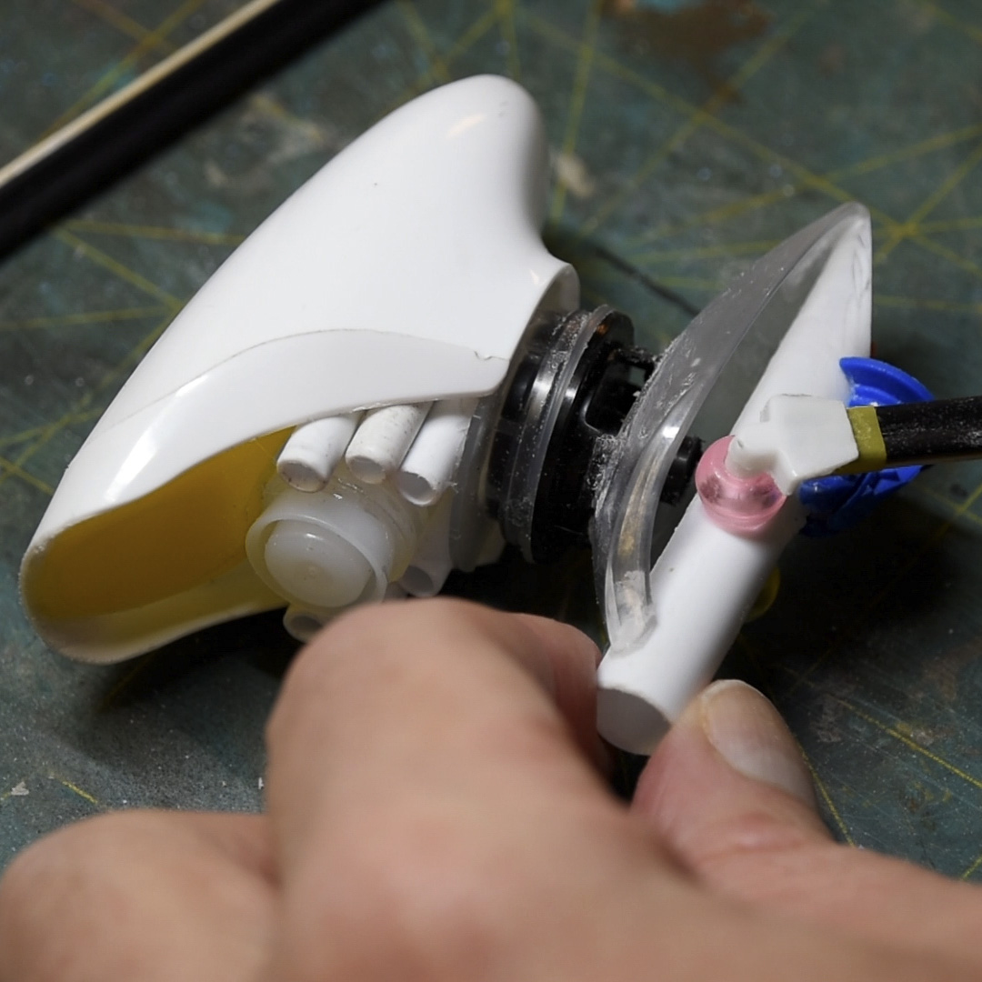
The alien tripod ship was trash-bashed from a spray bottle head, a collection of found bits of plastic and wood, and polymer clay. The building was constructed using the front facade from an Outland Models kit, 2mm styrene sheet and 3D printed details. Thanks for watching!


